 +86 13600513715
Leave Your Message
-
CONTACT NUMBER
-
 CONTACT NUMBER
 -
 CONTACT NUMBER
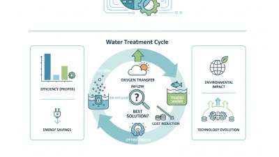
Choosing the right Tubular Membrane Diffuser is not a simple catalog decision. It affects oxygen transfer, blower energy, maintenance frequency, and treatment stability. The International Energy Agency reports that water services consume roughly 4% of global electricity. Wastewater aeration often represents the largest energy demand inside a treatment plant. A small diffuser mistake can therefore become a large operating cost.
Industry guidance supports a measured approach. The Water Environment Federation’s Manual of Practice No. 32 emphasizes oxygen-transfer testing, process conditions, and lifecycle performance. ASCE Standard 18-96 also provides methods for evaluating oxygen transfer in clean and process water. These references remind engineers that laboratory efficiency does not automatically match field performance. Temperature, wastewater solids, surfactants, diffuser depth, air flux, and membrane aging can change the result.
Look beyond initial airflow data. Examine pore structure, membrane material, active surface area, pressure loss, fouling resistance, and cleaning requirements. Picture a tank operating before sunrise, with uneven bubbles gathering beneath one grid section. That pattern may indicate poor distribution, blocked membranes, or insufficient header design. The diffuser alone may not be responsible.
There is no universal winner. A high-efficiency Tubular Membrane Diffuser may perform poorly under aggressive industrial wastewater conditions. Conversely, a more conservative model may deliver better reliability and lower lifecycle costs. This article explains how to compare diffuser designs, verify supplier claims, and match equipment with real process demands. Some choices remain uncertain. That is why field data should challenge assumptions before procurement.
How to Choose the Right Tubular Membrane Diffuser?
Understanding Tubular Membrane Diffuser Design and Operating Principles
A tubular membrane diffuser uses a flexible, perforated membrane stretched over a support tube. Air enters the tube and pushes against the membrane. The pores open, releasing many fine bubbles into the treatment tank. Small bubbles matter. Their larger surface area can improve oxygen transfer. However, performance depends on airflow, water depth, pore condition, and wastewater properties. Grease, solids, and biological growth may restrict the openings and increase pressure loss.
Tips: Match diffuser length and airflow with the blower system. Check the required submergence depth before installation. Review membrane material compatibility with temperature, chemicals, and cleaning methods. During operation, compare air pressure across diffuser zones. Uneven pressure can indicate fouling, blocked pores, or poor air distribution. Keep it practical.
In field inspections, operators often find that laboratory efficiency does not fully reflect tank performance. Actual wastewater changes daily. Temperature, viscosity, and suspended solids can alter bubble formation. A diffuser selected only by catalog oxygen-transfer data may disappoint. I would also question extremely low-pressure claims. Lower pressure sounds attractive, but stable operation and service access matter more. Inspect the membrane regularly, and record pressure trends before problems become visible.
A practical comparison of diffuser design parameters, operating conditions, materials, and selection criteria for biological wastewater aeration.
| Design or Operating Dimension | Typical Range or Option | How It Works | Why It Matters | Selection Guidance |
|---|---|---|---|---|
| Diffuser Configuration | Tubular membrane | Air passes through flexible membrane perforations, forming many small bubbles along the active tube length. | Provides a large effective aeration area and supports relatively uniform air distribution. | Suitable for activated-sludge tanks, oxidation ditches, equalization basins, and retrofit aeration systems. |
| Typical Tube Length | 0.5–2.0 m per diffuser element | Longer tubes provide more membrane area and can release air over a larger section of the basin. | Affects layout, air distribution, maintenance access, and the number of supports required. | Use longer elements where basin geometry permits; use shorter elements where access, lifting, or uneven loading is a concern. |
| Typical Tube Outside Diameter | Approximately 60–90 mm | The cylindrical membrane expands slightly as internal air pressure increases. | Influences membrane area, mechanical strength, air capacity, and diffuser spacing. | Confirm the actual diameter with the diffuser design because dimensions vary by construction and membrane material. |
| Membrane Material | EPDM, silicone, or PTFE-faced membrane | The membrane provides elastic perforations that open under air pressure and close when airflow stops. | Material affects chemical resistance, elasticity, temperature tolerance, aging, and fouling behavior. | Choose EPDM for many municipal applications; consider silicone for selected chemical or temperature conditions; consider PTFE-based surfaces where fouling or chemical exposure is critical. |
| Perforation Type | Slit or micro-perforated membrane | Slits or small openings regulate bubble release and reduce water entry when the diffuser is not aerating. | Controls bubble size, pressure loss, oxygen transfer, and resistance to clogging. | Match the perforation design to the required airflow range and wastewater fouling potential. |
| Nominal Bubble Size | Fine bubbles, commonly about 1–3 mm at release | Small bubbles create a high gas–liquid interfacial area and remain in contact with the liquid longer than coarse bubbles. | Smaller bubbles can improve oxygen transfer but may increase fouling sensitivity and pressure requirements. | Use fine-bubble tubes when energy-efficient oxygen transfer is the priority and air pretreatment is adequate. |
| Recommended Airflow per Tube | Often about 2–12 Nm³/h per metre of active length | Airflow changes membrane opening, bubble release, and pressure loss. | Operating outside the recommended range can cause poor distribution, excessive coalescence, or accelerated membrane fatigue. | Use the manufacturer’s tested minimum and maximum airflow; do not size only from nominal blower capacity. |
| Airflow Control Range | Typically designed around turndown of approximately 2:1 to 4:1 | Flexible perforations respond to changing internal air pressure and airflow. | Good turndown helps match aeration to variable biological oxygen demand. | Verify stable bubble release at minimum nighttime or low-load airflow before selecting the diffuser layout. |
| Clean-Water Pressure Loss | Commonly about 2–6 kPa at design airflow | Pressure is consumed by the membrane perforations, internal diffuser passages, and water depth. | Pressure loss directly contributes to blower power consumption. | Compare pressure loss at the actual design airflow, not only at a nominal test point. |
| Submergence Depth | Frequently 3–6 m, depending on basin design | Hydrostatic pressure increases approximately 9.8 kPa for every metre of water depth. | Greater depth improves gas contact time but requires higher blower discharge pressure. | Balance oxygen transfer benefits against blower energy, tank structure, and maintenance requirements. |
| Oxygen Transfer Performance | Highly site-specific; often evaluated by SOTE or SAE | Oxygen moves from bubbles into the liquid according to bubble area, contact time, oxygen deficit, mixing, and wastewater conditions. | Clean-water test results do not directly equal field performance in process wastewater. | Use field-corrected values that account for alpha factor, beta factor, temperature, fouling, and operating depth. |
| Standard Oxygen Transfer Efficiency | Fine-bubble systems may commonly achieve about 20–35% SOTE in suitable deep tanks | SOTE expresses oxygen transfer under standardized clean-water conditions at a defined depth and airflow. | It is useful for comparing systems but is not a guaranteed operating result. | Request the test conditions, active membrane area, airflow density, and correction method before comparing values. |
| Air Distribution Density | Often about 0.5–2.0 Nm³/h per metre of diffuser grid length | Spacing determines how evenly air is distributed throughout the aeration zone. | Uneven distribution can create dead zones, excessive local turbulence, or reduced oxygen transfer. | Design the grid for even coverage while maintaining access to headers, valves, and lifting points. |
| Operating Temperature | Commonly selected within approximately 5–40°C | Temperature affects membrane elasticity, oxygen solubility, biological demand, and blower performance. | Cold water holds more oxygen but may require different biological loading assumptions; high temperature accelerates material aging. | Check the membrane’s temperature rating against seasonal minimums, maximums, and cleaning conditions. |
| Wastewater Fouling Risk | Low, moderate, or high | Grease, suspended solids, scaling, iron, and biological growth can obstruct or stiffen membrane openings. | Fouling increases pressure loss and reduces oxygen transfer efficiency. | For high-risk wastewater, provide effective screening, air filtration, cleaning access, and a preventive maintenance plan. |
| Air Quality Requirement | Clean, oil-free, and adequately filtered blower air | Particles and oil aerosols can block perforations or degrade elastomeric membranes. | Air quality has a direct effect on service life and pressure stability. | Use suitable intake filtration, maintain filters, and prevent oil carryover from blower equipment. |
| Check-Valve Function | Membrane self-closing or dedicated check valve | When airflow stops, the membrane closes or the valve limits liquid intrusion into the air system. | Reduces water entry, header contamination, and restart problems. | Confirm protection against backflow during intermittent operation, blower shutdown, and maintenance. |
| Mixing Requirement | Depends on solids concentration and tank geometry | Rising bubbles transfer momentum to the liquid and generate circulation. | Insufficient mixing can cause solids settling even when oxygen transfer is adequate. | Verify that diffuser airflow provides required mixing at minimum operating conditions; add mechanical mixing if necessary. |
| Maintenance Access | Retrievable or fixed grid arrangement | Retrievable systems allow inspection or replacement without fully draining the basin; fixed systems may have lower initial complexity. | Access affects downtime, labor cost, safety, and lifecycle cost. | Select retrievable assemblies for deep or critical basins where draining is difficult or operational continuity is important. |
| Expected Service Life | Often approximately 5–10 years, depending on conditions | Membrane aging is influenced by airflow cycling, chemicals, temperature, cleaning, UV exposure, and fouling. | Service life affects replacement frequency and total cost of ownership. | Base the estimate on the actual wastewater, operating cycle, cleaning method, and documented field experience rather than a generic guarantee. |
| Best Primary Selection Criterion | Required oxygen delivery at acceptable blower power | The diffuser must deliver oxygen while maintaining uniform air distribution and manageable pressure loss. | The lowest purchase price may result in higher energy use or more frequent replacement. | Compare lifecycle cost, including energy, cleaning, replacement, access, and expected membrane life. |